Interesting, I have the Audiovox D1500A player (they are pretty cheap), they seem to be identical.
If you aren't using the High Voltage backlight power score it with a utility blade and snap it off, just be sure to do it along the free area between the High and Low voltage sides. (hold it up to a bright light, you will see an area where the light shines through).
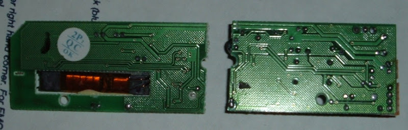
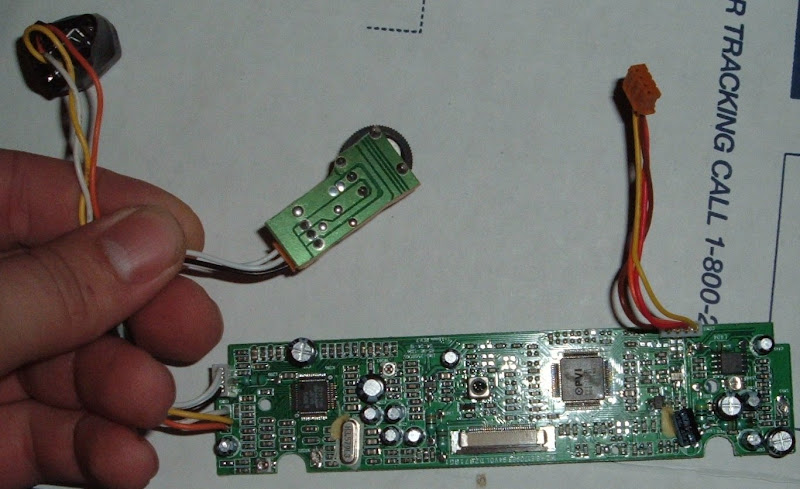
If you are using your own sound circuit, or making this one smaller, the same can be done, you will notice that I can free the contrast control, and the sound board is still fully functional, just solder the speakers directly from the source near the top headphone jack.

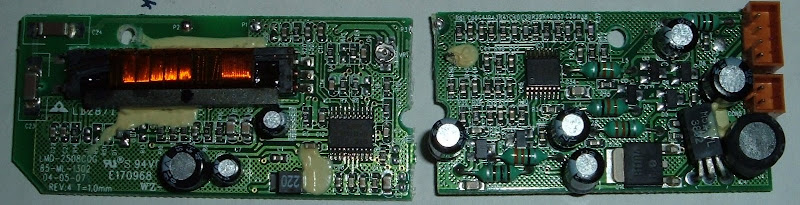
You can see that now there is a very nice and small setup, just plug in the new small power board and use it for your project, or your projector as the case may be, I have this one planned for a 50" projector

. The black thing above my thumb is an S-Video jack liberated from a DirecTivo, I look forward to the RGB inputs.
For full size pics, see here:
http://picasaweb.google.com/nubie07/AudiovoxD1500A
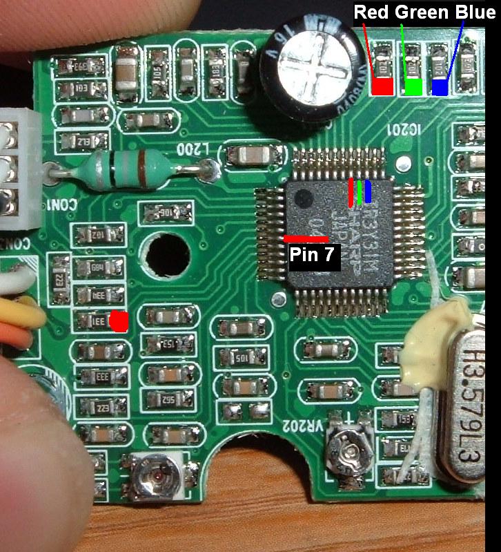
On Topic: if I solder RGB directly into that chip, will it just pick it up and display it? What happens to my S-Video jack? (I found out, see below)
If I use Powerstrip or a custom Nvidia resolution will I be able to connect this to VGA (RGB 480i) like the PSOne?
Edit: Pull pin 7 high for RGB, low for Video/S-Video I am assuming that this is already pulled low because of the S-Video input on my panel.
For S-Video/Video: Ground pin 5 for full composite to be accepted, connect to S-Video "C" if using S-Video input.
I wonder if I can hack the DVD player section to make RGB
, seems like the designers were making a competitor for the Squeezebox or the Leapfrog, one extra trace/wire for full RGB seems worth it to me.