Hi Folks,
I'm trying to collaborate with other Electronics Hobbyists working on Flash Carts. I'm currently working on a Flash cart for the SEGA GameGear. I just completed one for the Gameboy. My Background is in Electronics and Robotics. I'm still having some issues with the FLash interface, but I'm making progress which is motivating. I'm also working on one for the Sega Genesis.
I find the main problem I'm having is getting the proper ROM chip pinout connections. Allot of the available connection diagrams found online, are put together by other hobbyists and are not always 100% accurate. But regardless, I'll be getting it functioning soon.
Anyone else an avid Electronics Hobbyist? I would love to trade research if anyone is interested.
I have just recently completed a 5 part Instructional Video that shows how to build a Standard GameBoy Flash cart. It also covers Flash Programming procedures using a Willem Programmer and an ATMEL AT49F040 4Mbit Flash Chip or (512Kb of memory storage).
I will be putting another video together for the Genesis Flash Cart version as soon as I finish. But would love to chat with others that have successfully built similar models.
The video below is PART 1 of 5 for the GAMEBOY Flash Cart:
http://youtu.be/KzrYFI0aHVo
I look forward to your replies,
Regards,
-Gerry
__________________
My Electronics/Robotics YouTube Channel:
http://www.youtube.com/user/NLEproGUY" onclick="window.open(this.href);return false;
Do It Yourself GAMEBOY Flash Cartridge - Custom Electronics
Moderator:Moderators
Last edited by Gerry_MAN on Thu Aug 23, 2012 8:11 pm, edited 2 times in total.
-
nevermind1534
- Senior Member
- Posts:1977
- Joined:Fri Feb 06, 2009 1:36 pm
- Steam ID:nevermind1534
- Location:Detroit, MI
- Contact:
Re: Do It Yourself GAMEBOY Flash Cartridge - Custom Electronics
Thank you; I'll have to try this; I've been wanting a gameboy flash cart for a while now.
Kyo wrote:"does anyone here know how to fly a plane?"
"STAND BACK EVERYBODY, I HAVE A FAKE ID"
Re: Do It Yourself GAMEBOY Flash Cartridge - Custom Electronics
This deserves a bump!
Re: Do It Yourself GAMEBOY Flash Cartridge - Custom Electronics
http://www.smspower.org/Development/Documents" onclick="window.open(this.href);return false;
http://www.smspower.org/Development/SMSPagingChips" onclick="window.open(this.href);return false;
http://www.smspower.org/uploads/Development/devcart.txt" onclick="window.open(this.href);return false;
http://cgfm2.emuviews.com/txt/smstech.txt" onclick="window.open(this.href);return false;
http://gamesx.com/wiki/doku.php?id=sche ... megearcart" onclick="window.open(this.href);return false;
I do hope these links help.
Re: Do It Yourself GAMEBOY Flash Cartridge - Custom Electronics
Ahh yes..... thank you.
I had accessed these pages sometime ago. Good old SMSPower.
These are the cart edge connections that I'm having trouble with for the SEGA GG.
The real issue here is verification of the actual pinout connection for the Stock issued ROM chips that are used in the actual Sega GG carts.
There are allot of different pinout diagrams around on the net, so it's hard to confirm as to the actual connections. I think that is why there are very few DIY GG Flash carts around.
I'm now thinking there might be a specific Header needed in the ROM file image that is burnt the the FLash chips being used so that it will load properly.
Similar header files are used on some NES ROM images.
I'm currently playing around with this, so I'll wait an see what happens.
I'll keep you all posted.
Thanks again for the links regardless.
Cheers!
-Gerry

Re: Do It Yourself GAMEBOY Flash Cartridge - Custom Electronics
i will be waiting for the sega genesis one 
Re: Do It Yourself GAMEBOY Flash Cartridge - Custom Electronics
Ohh YeahH!!! That will be fun.
Genesis is sweet! Another one of my Fav systems. I love the old school stuff.
As for my Genesis Flash Cart:
I'm waiting on the Flash chips to arrive. This cart of course requires a 16-bit flash chip. Which simply means there is a 16 bit data I/O Bus.
However I put this project on the back burner until I make some headway with the GG version.
I have to discipline myself to try and work on one project at a time. It's so hard though.....so much stuff to play with.
I'm also so busy with school so time is tight. College is great though and my studies are related so I really enjoy it.
Electronics Technologist soon to be.
I can play with this stuff when I need to unwind.
Fun Stuff!
Later Folks,
-Gerry
Re: Do It Yourself GAMEBOY Flash Cartridge - Custom Electronics
http://devkits.handheldmuseum.com/GG_1MBEPROM.htm
http://tototek.com/pio/main1/SUBMENU/PA ... /ggpro.htm
... know what, I'll dig out my Game Gear and see if I can't figure it out.
edit: link noize
http://www.ridhughz.demon.co.uk/gamegear/Chuck_Rock.jpg" onclick="window.open(this.href);return false;
http://tototek.com/pio/main1/SUBMENU/PA ... /ggpro.htm
... know what, I'll dig out my Game Gear and see if I can't figure it out.
edit: link noize
http://www.ridhughz.demon.co.uk/gamegear/Chuck_Rock.jpg" onclick="window.open(this.href);return false;
Last edited by Snow_Cat on Sat Sep 18, 2010 11:39 pm, edited 1 time in total.
Re: Do It Yourself GAMEBOY Flash Cartridge - Custom Electronics
These commercial version Flash Carts are pretty sweet.
I had looked at them as well before.... for PCB Trace comparison but yet I'm still having issues getting my cart to run.
Well, I think I know what I'm doing tomorrow for my Sunday afternoon.
Fun Fun!!
Keep me posted on your findings.
And thanks for the help.
-Gerry
I had looked at them as well before.... for PCB Trace comparison but yet I'm still having issues getting my cart to run.
Well, I think I know what I'm doing tomorrow for my Sunday afternoon.
Fun Fun!!
Keep me posted on your findings.
And thanks for the help.
-Gerry
Re: Do It Yourself GAMEBOY Flash Cartridge - Custom Electronics
After a few hours of searching I've concluded that my Game Gear (games, and accessories, etc.) is lost.
Searching online I have foundedit: new trace
Then I matched the pins from the cart to the chip using the pinouts from SMS power, in Eagle.
docs.google.com2010.09.19.pdf
edit: obsolete/invalid
!WR looks scarry, but it is actually an indicator whether or not the CPU is writing data to the bus. I think that it is being as a chip enable to reduce bus collisions.
If you could post a scan or reasonably high-res photo of both sides I would be able to reproduce the PCB and could identify the remaining connections if they are present.
EDIT
There also used to be a geocities page about re-flashing the roms in the early GG cartridges (EEPROMS!) after they erased themselves. I know that a few of my games needed that treatment when I put it away.
looking only at components with ligic compatible data and address lines
EEPROMS
EPROMS
... Ack food.
Another mystery solved, the cartridge was designed for one EEPROM and substitution at the factory must have introduced this problem; it only appeared in the early carts either because of a standardization of part, or mfg's got smarter about the board design.
edit: inserted new trace from clear photo, and note how close pin 31 (commonly !WE) is to still being pulled to ground.
Searching online I have found
- www.ridhughz.demon.co.uk/Chuck_Rock.jpg
- a Game Gear cartridge that someone has depopulated, scored aggressively and had the gall to sell to a collector
- maxim smspower.orgPinouts
- a collection of information concering the SMS/GG cartridge pinouts, signals and logic
Spoiler:
Spoiler:
edit: obsolete/invalid
!WR looks scarry, but it is actually an indicator whether or not the CPU is writing data to the bus. I think that it is being as a chip enable to reduce bus collisions.
If you could post a scan or reasonably high-res photo of both sides I would be able to reproduce the PCB and could identify the remaining connections if they are present.
EDIT
There also used to be a geocities page about re-flashing the roms in the early GG cartridges (EEPROMS!) after they erased themselves. I know that a few of my games needed that treatment when I put it away.
looking only at components with ligic compatible data and address lines
EEPROMS
Spoiler:
... Ack food.
Another mystery solved, the cartridge was designed for one EEPROM and substitution at the factory must have introduced this problem; it only appeared in the early carts either because of a standardization of part, or mfg's got smarter about the board design.
edit: inserted new trace from clear photo, and note how close pin 31 (commonly !WE) is to still being pulled to ground.
Last edited by Snow_Cat on Tue Sep 21, 2010 11:47 am, edited 1 time in total.
Re: Do It Yourself GAMEBOY Flash Cartridge - Custom Electronics
A couple of comments here... Are you absolutely sure that that big ground plane isn't connected to the VSS pin but covered with silkscreen so you don't see it? The image is pretty blurry after all.Snow_Cat wrote:onsemi.comCAT28F512-D.pdfintersil.comFN8106.pdf
- Pin 1 -VPP Program/Erase Voltage Supply (tied to ground) not good!
Pin 16 -VSS Ground (open) very not good
Pin 32 -VCC Voltage Supply (+5V)
- Pin 1 -NC no connection (tied to ground) not good!
Pin 16 -VSS Ground (open) very not good
Pin 32 -VCC Voltage Supply (+5V)
Furthermore, NC pins can safely be grounded, and some cases this is even recommended. For example if you design a PCB for a lower capacity memory that is pin-compatible with higher capacities. Then, the lower capacity will have the higher address lines substituted with NC. If, for whatever reason, you don't have any spare address lines to connect them to for board compatibility with higher capacity memories, the best you can do is to at least ground them so they won't float. Of course, in other situations this might be a bad idea for compatibility, if a NC pin corresponds to an output on another pin-compatible chip, but the act of connecting an NC pin to ground is in itself not bad; the pin is simply not connected to anything inside the chip.
As for VPP, then... It, too, can be safely connected to ground. If you looked at the top of page 5 of the datasheet that you linked to, you'll see that it says that VPP may be anything from 0-6.5 V during read operation.
Out of those three, only the unconnected ground pin is an actual problem, if it is indeed unconnected.
Re: Do It Yourself GAMEBOY Flash Cartridge - Custom Electronics
One more thing... The CAT28F512 datasheet specifies a data retention of 10 years, so it's only natural that the chip will erase itself in time. Perhaps you should look at more than just the pinouts in the datasheets... 
Re: Do It Yourself GAMEBOY Flash Cartridge - Custom Electronics
I don't have my cartridges any more, however I did have a number that self-erased within the first couple of years (Columns, Shinobi, Loony Toons).
At the time this prompted me to open up the cartridges to see what I could. I noted that there were a variety of different styles of chips on identical boards, and that the chips in my Columns and Shinobi cartridges did not apper in cartridges I got later on. Before I could open it, Loony Toons got taken away by my dad who figured reflowing it with propane torch would fix the problem, and when I got it back no part of it resembled any chip or a cartridge at all.
If I could find a mirror of that cartridge hack (author made specific reference to Columns) I would also have some clean board art to go by.
And while I am not certain about most of this board art. Even if the image was not a terrible low resolution of a board that has clearly been damaged with some effort, there is no reason that pin 16 would not be enveloped in the ground mask the same as pins 1 and 32 are in theirs. Just as there is no reason to assume that either of these chips or their lik (while definitely being Address/Bus compatible) were ever in a Sega cart. edit: this is the point I was expecting an attack on, but clearly my trolling needs work.
If I still had I the actual cartridge I would un-solder the chip and see for myself. However, since this has clearly excited a response, I invite you to open up your cartridges and post the scans for all to see.
edit:grammar, +remark
Re: Do It Yourself GAMEBOY Flash Cartridge - Custom Electronics
Hi Folks, 
I'm going to post what I have done so far on this GameGear Flash cart project.
I'm using an ATMEL Flash chip for my cart, although I may try an EEPROM chip later in the future.... but regardless this is what I have done so far.
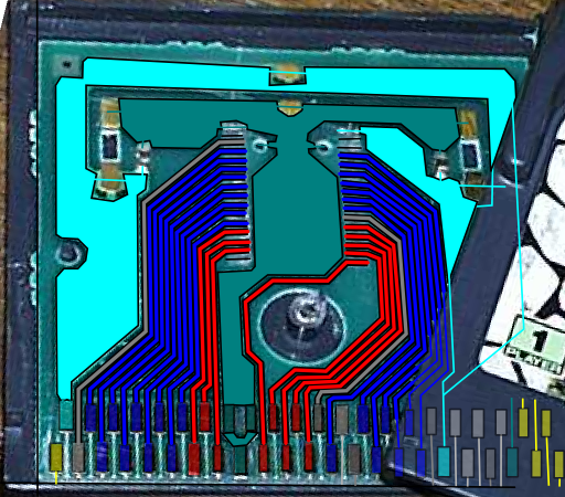
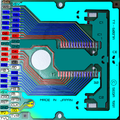
I used this wiring scheme for the cart Edge connections I found Online. I backtracked the traces and labeled the ROM PCB contacts accordingly.
I still need to try a few changes with the MREQ connection. I'm really thinking I may switch to an EEPROM if I can't get this sucker to work.

Below is the Cart scan of a standard Sega GAMEGEAR cart and came up with the wiring scheme that is shown in the following image.

My GameGear Cart Wiring scheme.

Here is a quick overlay of the wiring setup I used with my ATMEL AT49F040 Flash chip.....Forgive the crudity of this Graphic...I'm not in my Lab.

Shown Below are the Pinout connections for the ATMEL AT49F040 Flash Chip I am using.

So, I'm thinking my problem may be with the MREQ connection but not sure. I'm still messing around with a few other things.
So if anyone can see any misshaps I've made or have any suggestions to help let me know.
Here is my Current Mess of Wires and Solder! Yikes!!

Thanks Folks,
-Gerry
http://groups.yahoo.com/group/GAMEBOY_Electronics/
I'm going to post what I have done so far on this GameGear Flash cart project.
I'm using an ATMEL Flash chip for my cart, although I may try an EEPROM chip later in the future.... but regardless this is what I have done so far.
I used this wiring scheme for the cart Edge connections I found Online. I backtracked the traces and labeled the ROM PCB contacts accordingly.
I still need to try a few changes with the MREQ connection. I'm really thinking I may switch to an EEPROM if I can't get this sucker to work.
Below is the Cart scan of a standard Sega GAMEGEAR cart and came up with the wiring scheme that is shown in the following image.
My GameGear Cart Wiring scheme.
Here is a quick overlay of the wiring setup I used with my ATMEL AT49F040 Flash chip.....Forgive the crudity of this Graphic...I'm not in my Lab.
Shown Below are the Pinout connections for the ATMEL AT49F040 Flash Chip I am using.
So, I'm thinking my problem may be with the MREQ connection but not sure. I'm still messing around with a few other things.
So if anyone can see any misshaps I've made or have any suggestions to help let me know.
Here is my Current Mess of Wires and Solder! Yikes!!
Thanks Folks,
-Gerry
http://groups.yahoo.com/group/GAMEBOY_Electronics/
Re: Do It Yourself GAMEBOY Flash Cartridge - Custom Electronics
HaHA! 
So pin 16 is grounded. And I see that pins 31(commonly !WE), 30 (A17 NC) and 2 (A16 NC) are pulled low before board is perferated.
(also; Atmel and STmicro EEPROMS explicitly specifically say not to connect pin 1 when using PLCC xx28x010
or x27xx512.)
!WR is pulled low when the CPU is writing to the bus, it may act as an output inhibit.
So pin 16 is grounded. And I see that pins 31(commonly !WE), 30 (
(also; Atmel and STmicro EEPROMS explicitly specifically say not to connect pin 1 when using PLCC xx28x010
or x27xx512.)
!WR is pulled low when the CPU is writing to the bus, it may act as an output inhibit.