Hi,
Being 13 and new to electronics, I find it amazing that I actually kind of understand one thing about electronics - arcade wiring. For an upcoming project (involving an SNES, my favorite console), I decided to use arcade controls. However, I still have just a few questions that I know the electrical Jesuses here can help me with.
1. I found this - http://arcadecontrols.com/arcade_achilles.shtml" onclick="window.open(this.href);return false; - and this made it kind of clear. Solder the wires to the PCB and connect to the NO on the arcade button/joystick direction. However, I saw a tutorial on an Xbox 360 controller arcade mod that you need to scrape off some of the PCB and solder to the copper. Is this just limited to the Xbox controller or do I need to do the same for the SNES controller?
2. Another thing that was brought up was ground. I know that I can find one ground point and daisy chain it to all of the arcade buttons, but the main question is the ground itself. Where is ground on an SNES controller (or in general)?
Thanks!
Arcade Controls Wiring Questions
Moderator:Moderators
-
whatchitfoool
- Posts:29
- Joined:Sat Dec 31, 2011 4:23 pm
- PSN Username:whatchitfoool
- 360 GamerTag:whatchitfoool
- Steam ID:whatchitfoool
Re: Arcade Controls Wiring Questions
The ground is everywhere. It is all around us. Even now, in this very room. You can see it when you look under the hood of your car or inside your television. You can feel it when you go to work... when you go to church... when you get shocked on a heating register. It is the common thread that has been intertwined into everything to guide you to the truth; people are lazy and cheap.
there are 2 different types of grounds(excluding signal and floating ground), being a common ground in a circuit and earth ground.
earth ground obviously tell you what it is - a connection literally to earth. usually in the form of a big piece of copper jammed on water pipes in a home. this puts the common potential to the earth, so if protections fail in high-voltage systems it has a failsafe. a "ground" here is referring to a place to measure equalized potential at 0.
a common ground is referring to a common return path for current in an electrical system, that is then connected to the negative lead of the battery or other source. portable electronics and other things that run off batteries obviously don't have earth grounds. and there is no need to, but they do have common grounds.
not starting a long story that goes back to Edison and Tesla, power transmission is done with AC electricity. its AC because the voltage can be stepped up to lower the current, so thin wires can be used to span the long distances to wire citys with electricity. that means everyone has a common type of power coming out of there outlets. that's great, but just about nothing uses striate AC from a wall socket. most things run off of DC power, and at a lot lower voltage. to get AC down to a clean DC voltage where you want it, you need a power supply to handle converting it. and even if you use a simple bridge rectifier to do it, you wind up with a common ground on the output of where you are now supplying power from. so that wall-wart you plug into the AC outlet might not have a earth ground, it definitely has a common ground on the outside of that barrel plug you stick into the back of the SNES. this connection literally goes over the entire console, and out of the controller ports. i would assume its the black wire you see in the controller. the others are probably a clock, data,ect - but there will also be a Vcc wire- maybe red in color. metering across Vcc and ground would let you see the voltage.
you could probably wikipedia some of these more rudimentary principals and get a better worded explanation.
as for your PCB question, you should look up what a PCB actually is. its a layer of un-conductive who-cares with at least 1 thin layer of copper on a side. it has paths all over it that connect stuff in place of wires. these paths are called traces. traces are usually under a coating, to insulate them like a wire would be insulated. so unless you are going to be soldering to an exposed pad, you would have to very carefully scrape the protective layer off of a trace before you could make a connection with it. but if you are not soldering to it on a designed spot to be soldered on, you will probably rip the trace off. it isn't designed to be pulled on at all where it has a protective layer, so even a tiny pull will separate the copper from the pcb and rip it.
all the button's switch's "commons" would get wired to ground. then then controller buttons signal wires would get wired to the arcade pushbutton switches on the Normally Open side. that way when the button is pushed, it closes the contact and completes the circuit.
i hope all of that is at lease 1/2 coherent; im going to bed.
-
Haunted360
- Posts:1000
- Joined:Sat Jan 30, 2010 12:22 am
- PSN Username:Haunted360
- 360 GamerTag:Haunted 360
- Location:Australia
- Contact:
Re: Arcade Controls Wiring Questions
Sand lightly the NES pad's on the DATA side and solder each wire to the joystick.
As for the ground (-, Vss / GND), you solder one GND from the NES controller PCB, and put that in a daisy-chain to each ground terminal for the joystick.
You can see it right here!
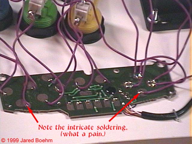
Same method for the buttons.
As for the ground (-, Vss / GND), you solder one GND from the NES controller PCB, and put that in a daisy-chain to each ground terminal for the joystick.
You can see it right here!
Same method for the buttons.