I based my pinouts on this:

and this:
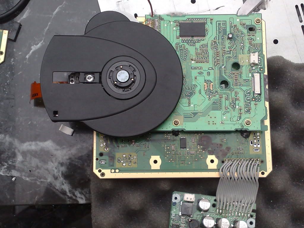
and these are my pictures:Gamelver wrote:
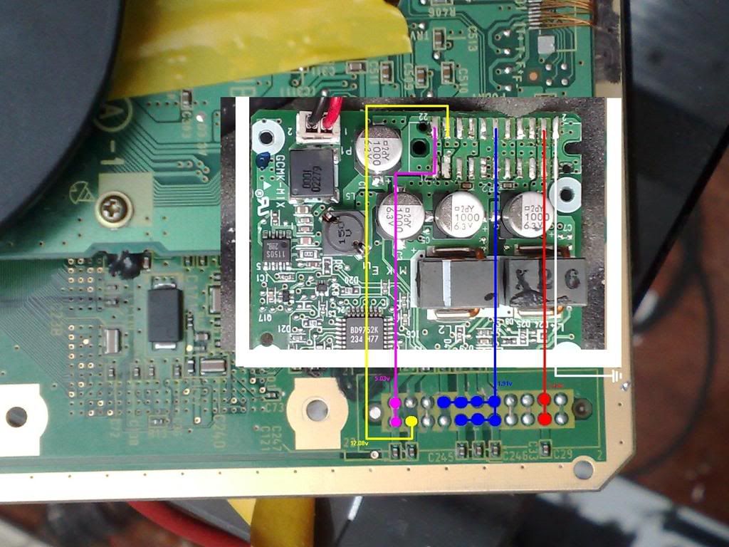
All right here's a pinout of the power regulator voltages:
first of all here's how the power regulator board looks:
all you really have to worry about are pins 12-22. pin 13 is 3.4v, pins 16-18 are 1.9v, pin 21 is 12v, and pin 22 is 5v. also you have to make sure you have ground.
here's the pins on the GC ( that box with the lines is the heatsink....I suck at paint):
pins 2 and 13 need 3.4v, pins 6,7,16,17,18,19 need 1.9v, pin 10 needs 12v, and pins 11 and 22 need 5v. just make sure that the pins that I've grouped together, like 6, 7, 16, 17, 18, 19 are connected together. they should be, though.
and that's how you only need 5 wires to attach the gc power regulator board to the GC board!!!!!!!!!!!!! that "bit of bad news" was that a gc regulator had fried and so I ordered another one....
* oh yeah if you turn on your GC and you don't get any sound, try getting the 12v not from the pin on the GC power regulator, but directly from the actual GC ac adapter. I also tried that from the 14.8v li-poly battery pack and it worked fine.


The last one is for easy following, incase the first 2 are hard to make out. I connected ground from pin 1 to pin 1, and that is probably my most likely problem. I also soldered all the pins connected in the picture together and connected one wire to them. Except for the 1.9V, I Connected 3 wires to that because it started with the most things to connect. Also I just realized I soldered pin 10 to pin 21 on the motherboard. Thats a possible problem too.
What do you all think?